Jack
Jr. Member
 
 Offline Offline
Posts: 73
Jack Kirkpatrick

|
 |
« on: July 25, 2015, 02:56:00 PM » |
|
I have an Atari Asteroids Deluxe that I just picked up today, broken. I replaced the power transistor because it was bad, but it still won't work. I noticed the voltage selector and molex connector are missing on the power "brick". Does anyone know if this is normal?
The monitor and light kicks on, however there is no voltage to the board.
|
|
|
|
|
 Logged
|
Jack
|
|
|
Jack
Jr. Member
 
 Offline Offline
Posts: 73
Jack Kirkpatrick

|
 |
« Reply #1 on: July 25, 2015, 03:52:40 PM » |
|
Update: Voltages at the test leads are 0.01-0.05 volts. I am thinking the big blue capacitor.
|
|
|
|
|
 Logged
|
Jack
|
|
|
|
iankellogg
|
 |
« Reply #2 on: July 25, 2015, 04:29:40 PM » |
|
First check fuses. Then check voltages on the power brick. Check the dc voltage between pin 1 and 5 of the 15 pin connector.  Should be something above 9v dc I doubt the big blue is bad. You won't be able to test that properly until you have a working game. However if you want to see if it's the problem just do a ac voltage test between pins 1 and 5 of the 25 pin connector and if it is more than maybe 3v ac then it might be bad. |
|
|
|
« Last Edit: July 25, 2015, 10:08:14 PM by iankellogg »
|
 Logged
|
|
|
|
Jack
Jr. Member
 
 Offline Offline
Posts: 73
Jack Kirkpatrick

|
 |
« Reply #3 on: July 25, 2015, 04:48:53 PM » |
|
0V between 1 and 5
Fuses are all good.
|
|
|
|
« Last Edit: July 25, 2015, 04:51:08 PM by MyTechtime »
|
 Logged
|
Jack
|
|
|
|
iankellogg
|
 |
« Reply #4 on: July 25, 2015, 10:11:21 PM » |
|
What is the ac voltage between 6 and 7
|
|
|
|
|
 Logged
|
|
|
|
Jack
Jr. Member
 
 Offline Offline
Posts: 73
Jack Kirkpatrick

|
 |
« Reply #5 on: July 25, 2015, 10:40:37 PM » |
|
About 36
|
|
|
|
|
 Logged
|
Jack
|
|
|
|
iankellogg
|
 |
« Reply #6 on: July 25, 2015, 10:42:34 PM » |
|
You need to get the power brick out of the cabinet to continue any more work on it. Either the diode bridge is broke somehow or a wire came loose. But there isn't anything more we can do with it in the cabinet.
|
|
|
|
|
 Logged
|
|
|
|
Jack
Jr. Member
 
 Offline Offline
Posts: 73
Jack Kirkpatrick

|
 |
« Reply #7 on: July 25, 2015, 10:44:02 PM » |
|
I've removed it a few times already. All the wiring inside it is fine.
|
|
|
|
|
 Logged
|
Jack
|
|
|
|
iankellogg
|
 |
« Reply #8 on: July 25, 2015, 10:46:05 PM » |
|
Have you checked the bridge? Does the bridge get AC?
|
|
|
|
|
 Logged
|
|
|
|
Jack
Jr. Member
 
 Offline Offline
Posts: 73
Jack Kirkpatrick

|
 |
« Reply #9 on: July 25, 2015, 10:48:39 PM » |
|
I haven't. How exactly do I test the bridge rectifier?
|
|
|
|
|
 Logged
|
Jack
|
|
|
|
iankellogg
|
 |
« Reply #10 on: July 25, 2015, 10:52:10 PM » |
|
The short answer is use the diode test on your multimeter and kind of probe between any two adjacent pins and you should have either 0.5v or OL. Test each pair both directions. You should have 4 0.5v results. And two 1.4v results.
The extra short answer. Have the thing flipped over and plug it in. Two pins will have AC voltage and two will have DC voltage.
|
|
|
|
|
 Logged
|
|
|
|
Jack
Jr. Member
 
 Offline Offline
Posts: 73
Jack Kirkpatrick

|
 |
« Reply #11 on: July 25, 2015, 11:21:25 PM » |
|
One pair is about .8 volts one way and nothing the other
Other pair is nothing either way
|
|
|
|
|
 Logged
|
Jack
|
|
|
|
iankellogg
|
 |
« Reply #12 on: July 25, 2015, 11:23:36 PM » |
|
You Have To Test Every combo of pairs. They are all interconnected. I should also mention there is going to be a pair where itblocks in both directions.
It's still easier to test voltages when it's on.
|
|
|
|
« Last Edit: July 25, 2015, 11:27:58 PM by iankellogg »
|
 Logged
|
|
|
|
Jack
Jr. Member
 
 Offline Offline
Posts: 73
Jack Kirkpatrick

|
 |
« Reply #13 on: July 25, 2015, 11:36:14 PM » |
|
All pairs look good except two. One does conduct either way and the other one gives .8 v one way instead of .4
|
|
|
|
|
 Logged
|
Jack
|
|
|
|
iankellogg
|
 |
« Reply #14 on: July 25, 2015, 11:39:44 PM » |
|
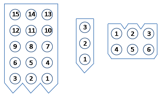
That sounds good. Just finish that up with checking the voltages. I don't remember if they label the pins or not. Either way here is all the common styles  |
|
|
|
|
 Logged
|
|
|
|
|


